Home automation electronics projectrf based wireless remote Circuit Diagram
BlogHome automation electronics projectrf based wireless remote Circuit Diagram It is widely used in many applications, including remote control systems, wireless security systems, and telemetry systems. Note: If we search the web for 433MHz RF modules, you will find many different variations of this module, but only the green module with variable capacitor works, at least from what we have tested. common RF channels and sniffable codes (insecure) scrambled sequential digital codes (secure) called Rolling Code method. IR with common IR carrier frequencies but unique codes (like TV remote) BUY a "Rolling-code" door opener with RF remote, Rx and switches, then reverse-engineer everything! (from electronics, mechanics, UX, packaging to quality).

The image of the short-range RF modules will be used since the connection is the same and the Long-range RF modules do not have a fritzing package. Transmitter Schematics. The transmitter schematics is quite simple, we only need to connect a push-button and the transmitter of the 315MHz transceiver to the Arduino as shown in the image below.

A Simple DIY Wireless Switch using 433Mhz RF Module Circuit Diagram
The latter provides Manchester encoding/decoding routines to balance the voltages used for the RF receiver gain averaging circuit. This instructable however, describes how you can make a Pic microcontroller talk to a cheap RF module (433MHz) through its USART port, to send data over a wireless link to another Pic.
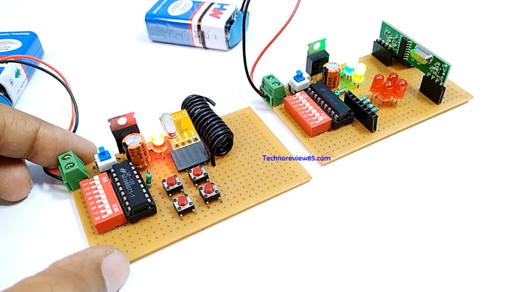
Here I'll show you how to make an approximately 100 meter range RF remote control circuit using RF modules, without the help of any microcontroller stage. To begin the assembly you will have to procure the following readymade RF modules and the respective encoder and decoder chips , for the present project we use the HOLTEKs modules: In this project, a wireless transmitter and receiver system using RF modules (RF Transmitter and RF Receiver) is implemented. An RF Transmitter and Receiver pair is used for wireless communication. The wireless data transmission is done using 433 MHz Radio Frequency signals that are modulated using Amplitude Shift Keying (ASK) Modulation technique.
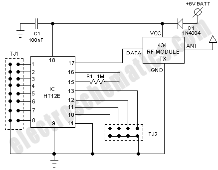
How can I use 433MHz RF Modules and HT12E/HT12D to create a wireless ... Circuit Diagram
Learn how to connect an nRF24L01+, two Arduinos, and a joystick to create your own two-channel wireless remote controller. The nRF24L01+ is an inexpensive 2.4 GHz wireless transceiver that interfaces with many microcontrollers. This project will use an nRF24L01+ to wirelessly connect a joystick to two servos. HT12D Typical Connection Diagram. DIN: Connected to the RF receiver module.; VT (Valid Transmission): Goes HIGH when valid data is received. Data Outputs (D0-D3): Drive relays, LEDs, or other control circuits. Working of HT12E and HT12D. HT12E (Encoder) Takes 4-bit parallel data and an 8-bit address.; Encodes and transmits serial data via the RF module when TE is low.
Description: Arduino 433Mhz RF Rx Tx-In this Tutorial, you will learn, how to make your own wireless remote control system using Arduino and 433MHz RF Radiofrequency transmitter and receiver modules. 433Mhz RF Rx Tx modules are quite famous for short-range uni-directional communication.These 433Mhz RF modules can be used for monitoring and controlling.
