Fire alarm Alarm Circuit Circuit Diagram
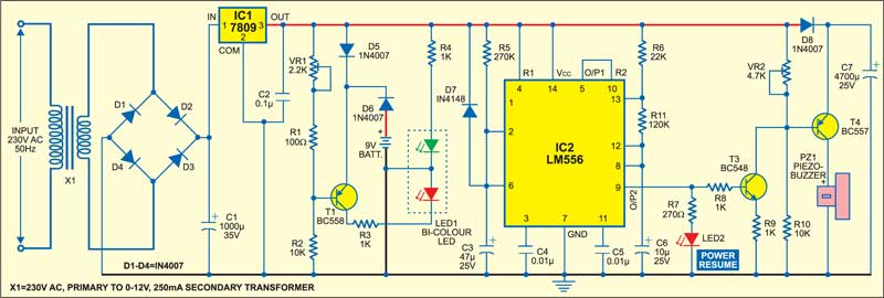
BlogFire alarm Alarm Circuit Circuit Diagram As soon as the mains power fails, the charge stored in the capacitor acts as a power-supply source for transistor T1. Since, in the absence of mains supply, the base of transistor is pulled 'low' via resistor R8, it conducts and sounds the buzzer (alarm) to give a warning of the power-failure. Power Supply Failure Alarm Circuit

A very simple 12V power supply failure alarm circuit. Low voltage, no stand-by current, piezo alarm. Working of Power Supply Failure Alarm. After soldering the components as per circuit diagram, connect the power supply and turn it on. Then to check the system, turn off the power supply and you will see buzzer start beeping as soon as you turn off the power.The working is same like an emergency light, which also turns on as soon as the power goes off.
Mains Power Supply Failure Alarm Circuit Circuit Diagram
By: Manisha Patel . How the power failure alarm works. This proposed circuit is connected to the power mains via the transformer T1. The AC voltage is rectified by the diode D1 and is filtered by C1.

A DIY Main Power Supply Failure Indicator Circuit designed by using few easily available components, Ensuring the reliability of power supplies is crucial in various electronic applications, ranging from consumer electronics to industrial systems. This simple circuit can help us to take appropriate action in case of power interrupt or failure. Using transistor, buzzer alarm, for DC power supply. Using transistor, buzzer alarm, for AC 220 V power supply. Using op amp, LED indicator, for DC power supply. Main Function. The main function of the proposed power failure indicator circuits is to alert or notify about a power failure situation in an electrical system.

5 Useful Power Failure Indicator Circuits Explained Circuit Diagram
The working of this power failure alarm circuit is very simple. A power Supply of 220 volts is turned on. This 220 volt is converted into 12 volts by the step-down transformer. Rectification is done by a diode bridge. The diode bridge consists of 4 diodes connected in series with each other. The rectified 12 volts are then supplied to the relay