Energy harvesting applications Circuit Diagram
BlogEnergy harvesting applications Circuit Diagram in wireless sensor networks). As traditional energy sources continue to deplete the cost of their utilization continues to increase. This fact has generated a growing interest in energy harvesting on a global level. Figure 1 illustrates how a simple energy harvesting scheme is employed to convert and store ambient energy into electrical energy. To further enhance the energy-harvesting performance of TENG, hybrid energy energy which was measured as an open-circuit voltage (dimension: 3 × 3 × 0.025 cm; dielectric constant: 3800 V/m

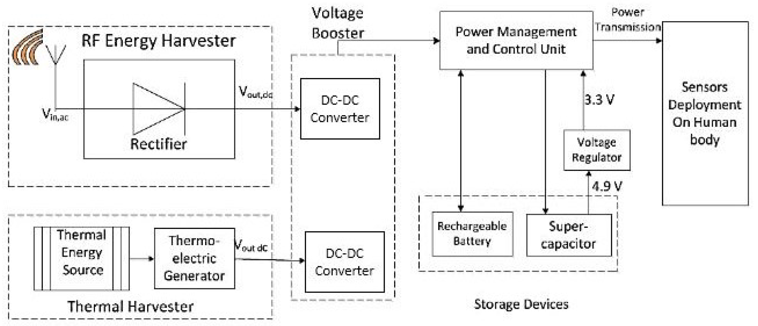
A hybrid energy harvesting scheme and system integrating radio frequency (RF) electromagnetic wave and solar energy based on optically transparent metasurface is proposed and constructed for the first time in this article. The scheme combines the RF link and the solar link through the high-efficiency transparent metasurface and rectifier circuit, the solar cell, and the power management
Hybrid energy harvesting based on piezoelectric and electromagnetic ... Circuit Diagram
The rectification of the piezoelectric system along with its results is discussed. Different circuits for amplification is studied and simulated to improve the voltage. All the practical experimental outputs and the different software used to gain these outputs are recorded. The various applications of the hybrid system are reviewed and discussed.

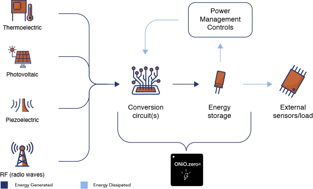
In today's research landscape focused on efficient energy utilization [2, 3], nanogenerators (NGs) and supercapacitors play pivotal roles in harvesting energy from microenergy sources [4, 5].However, the unpredictability of these sources challenges device reliability, prompting exploration into hybrid solutions that can harness energy from multiple sources simultaneously or intermittently. From Fig. 1, it can be seen that the energy acquisition converter consists of a piezoelectric, photoelectric transducer, interface circuit, power conversion module, acquisition module, and drive module. Composed of dynamic module and management control module. Optoelectronic, piezoelectric transducers, and interface circuits form the input terminal, which converts vibration energy and light
Advancements in hybrid energy harvesting: Combining triboelectric ... Circuit Diagram
This paper presents a comprehensive exploration of a Hybrid Energy Harvesting System designed to harvest energy from diverse sources, including 2.4 GHz and 5.8 GHz RF energy, electromagnetic (EM) energy, solar energy, and triboelectric energy. The proposed converter operates within a wide input voltage range, maximizing efficiency and stability. A reconfigurable RF-DC converter is used for
